Three.jsのBufferGeometryの使い方
この記事ではThree.jsのBufferGeometryの基本的な使い方を紹介します。
See the Pen
Three.js BufferGeometry Sample by Imai (@imai1)
on CodePen.
バージョン非互換が激しく過去の解説記事が当てにならなかったり、公式ドキュメントがあまり充実していなかったりで、結構苦労しました。この記事のコードはバージョンr142で動作確認しました。
BufferGeometryの概要
BufferGeometryクラスは、メッシュの頂点、面、法線、UV、マテリアル設定、etc... を管理する非常に重要なクラスです。BoxGeometryなどのプリミティブも、内部的にはBufferGeometryのサブクラスです。
Three.jsのユーザは、ジオメトリをコードで動的に生成したい場合などにBufferGeometryを直接作成します。
頂点および面情報の設定は頂点インデクスを用いない場合と用いる場合の二つがあります。どちらの方法かによって各種設定のやり方が異なるため、それぞれ分けて説明していきます。
頂点インデクスを用いない場合
例として、立方体を自前で作るケースを紹介します。まずコード全体を掲載し、後から各部分について説明します。冒頭のCodePenでは赤と青の立方体の生成部分に対応します。
// Cube
const originalVertices = [
  [-10, -10, -10],
  [+10, -10, -10],
  [+10, +10, -10],
  [-10, +10, -10],
  [-10, -10, +10],
  [+10, -10, +10],
  [+10, +10, +10],
  [-10, +10, +10],
];
const faces = [
  [1, 0, 2, 3],
  [0, 1, 5, 4],
  [1, 2, 6, 5],
  [2, 3, 7, 6],
  [3, 0, 4, 7],
  [4, 5, 6, 7],
]

function buildNonIndexedBufferCubeMesh() {
  const geometry = new THREE.BufferGeometry();

  const vertexBuffer = [];
  for (const face of faces) {
    const v0 = originalVertices[face[0]];
    const v1 = originalVertices[face[1]];
    const v2 = originalVertices[face[2]];
    const v3 = originalVertices[face[3]];
    vertexBuffer.push(...v0.concat(v1, v2)); // a triangle
    vertexBuffer.push(...v2.concat(v3, v0)); // a triangle
  }

  const vertices = new Float32Array(vertexBuffer);
  geometry.setAttribute("position", new THREE.BufferAttribute(vertices, 3));

  const numVertices = vertexBuffer.length / 3;
  geometry.addGroup(0, numVertices / 2, 0);
  geometry.addGroup(numVertices / 2, numVertices / 2, 1);

  geometry.computeVertexNormals();

  const material0 = new THREE.MeshLambertMaterial({color: 0xFF0000});
  const material1 = new THREE.MeshLambertMaterial({color: 0x0000FF});
  const materials = [material0, material1];
  const mesh = new THREE.Mesh(geometry, materials);
  return mesh;
}
頂点および面の設定
まず、頂点および面の設定はコード内の以下の箇所です。
  const vertices = new Float32Array(vertexBuffer);
  geometry.setAttribute("position", new THREE.BufferAttribute(vertices, 3));
BufferAttributeの第一引数は、面、頂点、頂点成分の順に並べたFloat32Array型の一次元配列を指定します。具体的には以下のような並びの配列です。
- 面1の頂点1の成分1
- 面1の頂点1の成分2
- 面1の頂点1の成分3
- 面1の頂点2の成分1
- 面1の頂点2の成分2
- 面1の頂点2の成分3
- 面1の頂点3の成分1
- 面1の頂点3の成分2
- 面1の頂点3の成分3
- 面2の頂点1の成分1
なお、BufferAttributeの第二引数は公式によると成分のサイズの3とのことです。面内の頂点数が3で固定なのか可変なのかは確たる証拠が見つけられていませんが、特に設定方法が見当たりませんし、WebGLだと3で固定ですし、おそらく前者なのではないかと……。なお、昔のバージョンではFace3 Face4というクラスがあったようです。
buildNonIndexedBufferCubeMeshでは、以下の部分でoriginalVertices facesをvertexBufferに変換しています。
  const vertexBuffer = [];
  for (const face of faces) {
    const v0 = originalVertices[face[0]];
    const v1 = originalVertices[face[1]];
    const v2 = originalVertices[face[2]];
    const v3 = originalVertices[face[3]];
    vertexBuffer.push(...v0.concat(v1, v2)); // a triangle
    vertexBuffer.push(...v2.concat(v3, v0)); // a triangle
  }
マテリアル設定
各面にマテリアルを設定するためには、頂点を複数のグループに分け、グループごとにマテリアルのインデクスを設定します。コードは以下の部分です。
  const numVertices = vertexBuffer.length / 3;
  geometry.addGroup(0, numVertices / 2, 0);
  geometry.addGroup(numVertices / 2, numVertices / 2, 1);
addGroupの第一引数はグループ化する"頂点"の開始インデクスです。頂点成分や面の開始インデクスではないことにご注意ください。言い換えると、vertexBufferの添字の[addGroupの第一引数×3]番目から始まる頂点列をグループ化します。
同様に、グループ化する第二引数は頂点の個数です。第三引数はグループに割り当てるマテリアルのインデクスです。
なお、公式ドキュメントによるとグループごとに描画呼び出しが走るとのことなので、同じマテリアルの頂点は並び替えて一つのグループにまとめた方が描画が高速かもしれません。
法線設定
面の法線を計算し、その平均値を頂点法線とする場合は、computeVertexNormalsを実行します。
geometry.computeVertexNormals();
手動で別の法線を設定したい場合はsetAttributeを利用するのではないかと思いますが、確認できていません。
なお、法線を何も設定しないとメッシュが描画されません。
頂点インデクスを用いる場合
まずはコード全体です。冒頭のCodePenでは水色と黄色の立方体の生成部分に対応します。
function buildIndexedBufferCubeMesh() {
  const geometry = new THREE.BufferGeometry();

  const vertexBuffer = originalVertices.flat();

  const vertices = new Float32Array(vertexBuffer);
  geometry.setAttribute("position", new THREE.BufferAttribute(vertices, 3));

  const indices = [];
  for (const face of faces) {
    indices.push(face[0], face[1], face[2]);
    indices.push(face[2], face[3], face[0]);
  }
  geometry.setIndex(indices);

  const numIndices = indices.length;
  geometry.addGroup(0, numIndices / 2, 0);
  geometry.addGroup(numIndices / 2, numIndices / 2, 1);

  geometry.computeVertexNormals();

  const material0 = new THREE.MeshLambertMaterial({color: 0xFFFF00});
  const material1 = new THREE.MeshLambertMaterial({color: 0x00FFFF});
  const materials = [material0, material1];
  const mesh = new THREE.Mesh(geometry, materials);
  return mesh;
}
頂点および面の設定
頂点の設定はコード内の以下の箇所です。
  const vertices = new Float32Array(vertexBuffer);
  geometry.setAttribute("position", new THREE.BufferAttribute(vertices, 3));
頂点インデクスを用いる場合は、setAttribute("position", ...)には、ジオメトリの各頂点の成分を一次元配列に潰した形状のバッファを指定します。buildIndexedBufferCubeMeshでは単にoriginalVertices.flat();とすれば十分です。
面を設定するためは、頂点のインデクスを並べた配列をsetIndexに与えます。
  const indices = [];
  for (const face of faces) {
    indices.push(face[0], face[1], face[2]);
    indices.push(face[2], face[3], face[0]);
  }
  geometry.setIndex(indices);
マテリアル設定
面のグループ化およびマテリアル設定は以下の部分です。
  const numIndices = indices.length;
  geometry.addGroup(0, numIndices / 2, 0);
  geometry.addGroup(numIndices / 2, numIndices / 2, 1);
頂点インデクスを用いる場合も、addGroupの第一引数・第二引数は頂点インデクスの個数です。言い換えると、(頂点・面が同じ形状・並びならば)頂点インデクスを用いない場合にaddGroupを呼び出す場合と同じ引数を与えるようです。
環境設定
カメラや光源を設定しているだけですが載せておきます。
function main() {
  // scene, add mesh
  var scene = new THREE.Scene();

  const nonIndexedCubeMesh = buildNonIndexedBufferCubeMesh();
  scene.add(nonIndexedCubeMesh);

  const indexedCubeMesh = buildIndexedBufferCubeMesh();
  indexedCubeMesh.position.set(30, 0, 0);
  scene.add(indexedCubeMesh);

  // camera, light, renderer
  const camera = new THREE.OrthographicCamera(-60, +60, 35, -35, 1, 1000);
  camera.position.set(-90, -90, 60);
  camera.up.set(1, 1, 1);
  camera.lookAt(new THREE.Vector3(0, 0, 0));
  scene.add(camera);

  const directionalLight = new THREE.DirectionalLight(0xffffff, 0.5);
  directionalLight.position.set(-10, 15, 50);
  scene.add(directionalLight);

  const directionalLightTarget = new THREE.Object3D();
  scene.add(directionalLightTarget);
  directionalLight.target = directionalLightTarget;

  const ambientLight = new THREE.AmbientLight(0xffffff, 0.5)
  scene.add(ambientLight);

  var renderer = new THREE.WebGLRenderer();
  renderer.setSize(window.innerWidth, window.innerHeight);
  document.body.appendChild(renderer.domElement);
  renderer.render(scene, camera);
}

main();
将来課題
UVの設定など、この記事で説明していない要素がまだたくさん残っていますので、解決したら記事を更新しようと思います。
ビル群のプロシージャル生成 ver.0.1
ビル群をプロシージャル生成するプログラムをJavaScript+Three.jsで書いてみました。
See the Pen
[WIP] procedural generation for buildings by Imai (@imai1)
on CodePen.
既製品の商用ライブラリにもっと凄いのがありますが、自分で作ってみたくなったので……。
この記事では、このプログラムについて解説していきます。
環境設定
まずは、CDNからThree.jsを読み込みます。
<script src="https://unpkg.com/three@0.142.0/build/three.min.js"></script>
JavaScriptコードの一番外側の処理はmain関数にまとめてあります。
function main() {
  const WIDTH = window.innerWidth;
  const HEIGHT = window.innerHeight;

  const renderer = new THREE.WebGLRenderer({antialias:true});
  renderer.setSize(WIDTH, HEIGHT);
  renderer.setClearColor(0xDDDDDD, 1);
  document.body.appendChild(renderer.domElement);

  const [scene, camera] = initializeScene();

  const width = 200;
  const height = 200;
  scene.add(makeBaseMesh(width, height));
  addAvenueMesh(scene, 6, 3);
  //scene.add(makeBuildingMesh(30, 30, 0.5, 4.0, 3.0, 8));

  /*
  function render() {
    requestAnimationFrame(render);
    renderer.render(scene, camera);
  }
  render();
  */
  renderer.render(scene, camera);
}

main();
WebGLRendererの設定や利用に関するごく普通のコードだと思います。詳細についてはThree.jsの解説記事をご覧ください。
カメラと光源はinitializeScene関数で設定しています。また、床面の大きな板はmakeBaseMesh関数で生成しています。
function initializeScene() {
  const scene = new THREE.Scene();

  scene.fog = new THREE.Fog(0x0, 120, 220);

  const camera = new THREE.OrthographicCamera(-120, +120, 70, -70, 1, 1000);
  camera.position.set(-90, -90, 60);
  //camera.rotation.set(Math.PI / 4, 0, -Math.PI / 4);
  camera.up.set(1, 1, 1);
  camera.lookAt(new THREE.Vector3(0, 0, 0));
  scene.add(camera);

  const directionalLight = new THREE.DirectionalLight(0xffffff, 0.5);
  directionalLight.position.set(-10, 15, 50);
  scene.add(directionalLight);

  const directionalLightTarget = new THREE.Object3D();
  scene.add(directionalLightTarget);
  directionalLight.target = directionalLightTarget;

  const ambientLight = new THREE.AmbientLight(0xffffff, 0.5)
  scene.add(ambientLight);

  return [scene, camera];
}

function makeBaseMesh(xSize, ySize) {
  const geometry = new THREE.PlaneGeometry(xSize, ySize);
  const material = new THREE.MeshLambertMaterial({color: 0xEAEFF2});
  const mesh = new THREE.Mesh(geometry, material);
  return mesh;
}
複数のビル群の生成
一つのビルを生成する関数はmakeBuildingMeshですが、先に、これを利用してビル群を生成する部分を紹介します。
ビル群の生成はaddAvenueMesh関数で実施しています。
function addAvenueMesh(scene, xSize, ySize) {
  const xUnit = 20;
  const yUnit = 24;
  for (let y = 0; y < ySize; ++y) {
    for (let x = 0; x < xSize; ++x) {
      // Setup random parameters for a building.
      const widthOfBuilding = Math.random() * 2 + 18;
      const firstFloorLevel = Math.random() * 0.4 + 0.3;
      const floorHeight = Math.random() * 1.5 + 3;
      const ceilingHeight = Math.random() * 0.5 + 2.5;
      const numFloors = Math.floor(Math.random() * 10 + 2);

      // Generate a mesh of a building.
      const mesh = makeBuildingMesh(
        widthOfBuilding,
        widthOfBuilding,
        firstFloorLevel,
        floorHeight,
        ceilingHeight,
        numFloors
      );

      // Move the mesh.
      const px = x * xUnit - xSize * xUnit / 2;
      const py = y * yUnit - ySize * yUnit / 2;
      mesh.position.set(px, py, 0);
      scene.add(mesh);
    }
  }
}
パラメータをランダムに設定してmakeBuildingMeshを実行、という処理を碁盤状に座標を変えながら繰り返しているだけです。
ビルの生成
最後にmakeBuildingMeshの紹介です。
makeBuildingMesh関数の全体像
まずは、ビルの形状を実際に作る処理を後回しにして、先に関数の全体像を紹介します。
このコードでは、Three.jsのBufferGeometryクラスを利用して、柱や窓などの面を一つ一つ手作りしていく方法でビルを生成しました。makeBuildingMeshでは、BufferGeometryの初期化や、面を張るサブルーチンaddFace、直方体を置くサブルーチンaddCubeなどを定義し、そのあとビルの形を定義して、最後に各種データをまとめてメッシュ化します。
function makeBuildingMesh(xWidth, yWidth, firstFloorLevel, floorHeight, ceilingHeight, numFloors) {

  ///////////////////////////////////////////////////////////
  // Preprocess.
  ///////////////////////////////////////////////////////////

  const geometry = new THREE.BufferGeometry();
  const rawVertices = new Array();

  let numVertices = 0;
  function addFace(a, b, c, d, materialIndex) {
    rawVertices.push(...a.concat(b, c, c, d, a));
    geometry.addGroup(numVertices, 6, materialIndex);
    numVertices += 6;
  }

  function addCube(x, y, z, xWidth, yWidth, height, materialIndex) {
    const vertices = [
      [x, y, z],
      [x + xWidth, y, z],
      [x + xWidth, y + yWidth, z],
      [x, y + yWidth, z],
      [x, y, z + height],
      [x + xWidth, y, z + height],
      [x + xWidth, y + yWidth, z + height],
      [x, y + yWidth, z + height],
    ];
    addFace(vertices[3], vertices[2], vertices[1], vertices[0], materialIndex);
    addFace(vertices[0], vertices[1], vertices[5], vertices[4], materialIndex);
    addFace(vertices[1], vertices[2], vertices[6], vertices[5], materialIndex);
    addFace(vertices[2], vertices[3], vertices[7], vertices[6], materialIndex);
    addFace(vertices[3], vertices[0], vertices[4], vertices[7], materialIndex);
    addFace(vertices[4], vertices[5], vertices[6], vertices[7], materialIndex);
  }

  ///////////////////////////////////////////////////////////
  // Define the shape of a building.
  ///////////////////////////////////////////////////////////

  // ビルの形状を作る処理は後述

  ///////////////////////////////////////////////////////////
  // Postprocess.
  ///////////////////////////////////////////////////////////

  // itemSize = 3 because there are 3 values (components) per vertex
  const vertices = new Float32Array(rawVertices);
  geometry.setAttribute("position", new THREE.BufferAttribute(vertices, 3));
  geometry.computeVertexNormals();

  const wallMaterial = new THREE.MeshLambertMaterial({color: 0xEAEFF2});
  const windowMaterial = new THREE.MeshBasicMaterial({color: 0xBBBB00, side: THREE.DoubleSide});
  windowMaterial.opacity = 0.6;
  windowMaterial.transparent = true;
  const materials = [wallMaterial, windowMaterial];
  const mesh = new THREE.Mesh(geometry, materials);
  return mesh;
}
L-Systemについて
ビルの形状はL-Systemによって定義します。
Lindenmayerが提案したオリジナルのL-System以外にも様々な類似手法がL-Systemと呼ばれているため、その上でバシッと定義を説明せよと言われると私のような素人には難しいのですが、誤解を恐れずに大雑把に言えば、L-Systemとは記号の置換ルールの再帰適用によって複雑な形状やルールを生成するための手法です。
例えば、
街 とは { (1, 1)に家があって、(2, 1)に店があって、(3, 1)に道路があって、... }

(x, y)に家 とは { (x, y)に壁があって、(x+0.1, y)に家具があって、... }

(x, y)に店 とは { ... }

(x, y)に道路 とは { ... }という風に定義して、「〇〇とは」を左辺から右辺に各々変換していくと、最終的に「街」は
街とは { (1, 1)に壁があって、(1.1, 1)に家具があって、... }という風に、ローレベルなオブジェクトの集合に変換することができます。
実際には、最終的に変換されるローレベルなオブジェクトがCGライブラリのオブジェクトに置き換えられるように各部品を定義してあげると、L-Systemによって3DCGモデルを生成することができます。CGライブラリのオブジェクトとは、今回でいうとThree.jsの面や頂点や、それをラップしたaddFace addCubeなどです。
また、「〇〇とは { ... }」は、プログラミング言語における関数と全く同型の構造になっていますので、各変換処理は関数定義によって表すことができます。
ビルの形状の定義
以上を踏まえて、実際のビル形状の定義を紹介します。
まず、建物の基礎(Base)はaddBaseによって定義します。
  function addBase(x, y, z, xWidth, yWidth, height, numFloors) {
    // add a cube for base.
    addCube(x, y, z, xWidth, yWidth, height, 0);

    // add floors.
    addFloor(x, y, height, xWidth, yWidth, floorHeight, ceilingHeight, numFloors);
  }

  addBase(-xWidth / 2, -yWidth / 2, 0, xWidth, yWidth, firstFloorLevel, numFloors);
基礎にあたる大きな直方体を一つ定義して、その上にフロアを積み重ねるだけです。
一つ一つのフロアはaddFloorによって定義します。かなり大きいので実際の実装はCodePenをご覧いただくとして、擬似コードで説明すると以下のようになります。
  // 複数の階で共通のパラメータを定義

  function addFloor(x0, y0, z0, xWidth, yWidth, floorHeight, ceilingHeight, numFloors) {
    // 柱や窓などを生成するサブルーチンを定義
    // (一部パラメータをクロージャで引き継ぐために内部関数として定義した)

    // 四隅の柱を定義

    if (windowPattern == 0) {
      // 四辺に窓を定義
    } else if (windowPattern == 1) {
      // 四辺に窓、柱、窓、柱、...のパターンを定義
    }

    // add a ceiling.
    addCube(x0, y0, z0 + ceilingHeight, xWidth, yWidth, floorHeight - ceilingHeight, 0);

    // add a next floor
    if (numFloors > 1) {
      addFloor(x0, y0, z0 + floorHeight, xWidth, yWidth, floorHeight, ceilingHeight, numFloors - 1);
    }
windowPatternとして新しいパターンを定義すれば、別の窓枠配置も追加することができます。
また、上の階はaddFloorを再帰的に呼び出して生成するようになっています。for文で各階を定義するよう実装しなかったのは、L-Systemが元々再帰的なものだからというのもありますが、上の階をwindowPatternのようなやり方で別のデザインに変更できるよう将来的な拡張を考慮したためです。
将来課題
いくらでも改良できますが、例えば以下のような課題が考えられます。
- 1Fの入り口パターンの追加
- 窓枠のパターンの追加
- 柱のパターンの追加(外壁に大きな柱のないビルなど)
- 窓のない面を持つビルの追加
- 屋上のパターンの追加
- 外壁の色のパターンの追加
- 窓の色のパターンの追加
"Decoding A City In A Bottle"を読んで
2022年4月に以下のツイートが一部界隈で話題になったようです。筆者は今更知りました。
A City in a Bottle 🌆
— Frank Force 🌻 (@KilledByAPixel) 2022年4月22日
<canvas style=width:99% id=c onclick=setInterval('for(c.width=w=99,++t,i=6e3;i--;c.getContext`2d`.fillRect(i%w,i/w|0,1-d*Z/w+s,1))for(a=i%w/50-1,s=b=1-i/4e3,X=t,Y=Z=d=1;++Z<w&(Y<6-(32<Z&27<X%w&&X/9^Z/8)*8%46||d|(s=(X&Y&Z)%3/Z,a=b=1,d=Z/w));Y-=b)X+=a',t=9)> pic.twitter.com/N3WElPqtMY
このコードは、以下のようなビル群っぽい風景をレイトレーシングした動画を生成するGenerative Artです。

元ツイートには実際の動画が貼り付けられていますので、ぜひ見てみてください。
有志の方々の解析
何人かの方が、読みやすく書き直したコードを紹介しています。
大まかにまとめると、A City In A Bottleは以下の処理を行なっているようです。
setIntervalで連続して描画処理を呼び出す。呼び出し毎にカメラ位置を右にずらす。- 一重ループでカメラの各ピクセル方向ごとにレイを飛ばす。ループ変数を除算と剰余で二次元の方向に分解することで、一重ループで二次元の走査を実現している。
- 一重ループでレイ=直線の媒介変数を少しずつ動かす。動かす毎に建物との衝突検知を判定する。
- 建物に衝突していたら窓枠っぽい模様を塗る。
- 一重ループでレイ=直線の媒介変数を少しずつ動かす。動かす毎に建物との衝突検知を判定する。
- 一重ループでカメラの各ピクセル方向ごとにレイを飛ばす。ループ変数を除算と剰余で二次元の方向に分解することで、一重ループで二次元の走査を実現している。
なお、座標系は左手系です。すなわち左右がx、高さがy、奥行きがzです。
筆者による解析(?)
レイの衝突判定に記述されている建物の形状を固定カメラで描画してみました。
以下は"Decoding A City In A Bottle"の解析の一部コードを少し改変したものです。
const GROUND_PLANE = 6;
const CITY_DISTANCE = 32;
const AVENUE_WIDTH = 27;
const AVENUE_PERIOD = 99;
const BUILDING_WIDTH = 9;
const BUILDING_DEPTH = 8;
const BUILDING_HEIGHT = 45;

function buildingHeight(X, Z) {
  return (CITY_DISTANCE<Z&AVENUE_WIDTH<X%AVENUE_PERIOD&&X/BUILDING_WIDTH^Z/BUILDING_DEPTH)*8%(BUILDING_HEIGHT+1);
}
ビルの高度マップ 3Dバージョン
x-z毎に高さがbuildingHeightのキューブを並べて描画するThree.jsのコードです。
See the Pen
Decoding "A City In A Bottle", 3D version by Imai (@imai1)
on CodePen.
ビルの高度マップ 2Dバージョン
x-z毎にbuildingHeightで色分けしてキャンバスにfillRectで色付けしたものです。
See the Pen
Decoding "A City In A Bottle", 2D version by Imai (@imai1)
on CodePen.
ビルの高度マップ ランダムバージョン
以下のように、Math.randを使って生成した通常の乱数でも似たような結果になるようです。
const buffer = new Array(30);
for (let z = 0; z < buffer.length; ++z) {
  buffer[z] = new Array(buffer.length);
}

function getBuffer(x, z) {
  const X = Math.floor(x / BUILDING_WIDTH);
  const Z = Math.floor(z / BUILDING_DEPTH);
  if (buffer[Z][X] == undefined) {
    buffer[Z][X] = (Math.random() - 0.1) * 10000;
  }
  return buffer[Z][X];
}

function buildingHeight(X, Z) {
  return (CITY_DISTANCE<Z&AVENUE_WIDTH<X%AVENUE_PERIOD&&getBuffer(X, Z))*8%(BUILDING_HEIGHT+1);
}
See the Pen
Untitled by Imai (@imai1)
on CodePen.
反対に言えば、多次元座標の各成分のXORをとると簡易的な乱数になるようですね。周期は短いのかもしれませんが、このような用途では便利そうです。
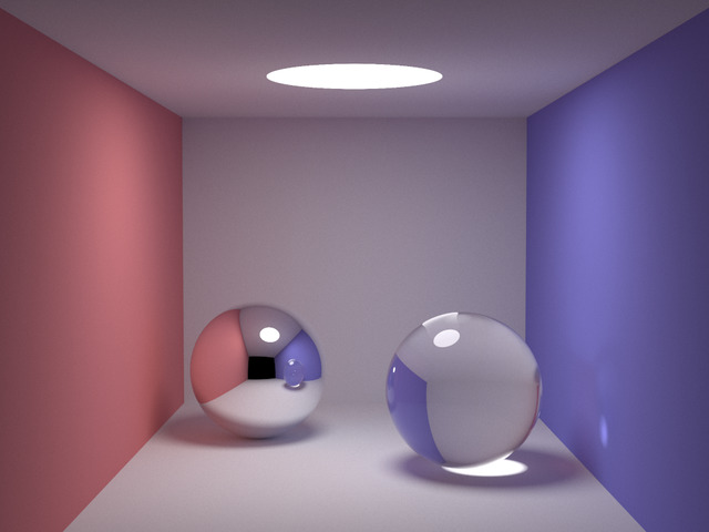
グローバルイルミネーションを99行のC++で
余談ですが、以下の画像を生成する99行のC++というのもあります。

Three.jsでミニチュアの箱庭を制作 ver.0.1
Three.jsでミニチュアの箱庭?っぽいものを作ってみました。
See the Pen
Untitled by Imai (@imai1)
on CodePen.
コード解説
準備
以下のライブラリを読み込みます。
<script src="https://unpkg.com/three@0.142.0/build/three.min.js"></script>
<script src="https://unpkg.com/three@0.142.0/examples/js/utils/BufferGeometryUtils.js"></script>
高度マップの生成
グレーの土台は以下の手順で作成しました。
- 2次元の高度マップを生成する。
- 各座標毎に高さの分だけ1x1x1のキューブを積み重ねる。
高度マップはDiamond-Squareアルゴリズムで生成しました。runDiamondSquareAlgorithm関数がこの処理に対応します。
以下の記事に少しだけ詳しめの説明があります。よろしければそちらもご覧ください。
生成した高度マップに対してキューブを積み重ねる処理はmakeMapMesh関数にまとめました。
function makeMapMesh(map, bottom) {
  const boxGeometries = [];
  function addBoxGeometry(x, y, z) {
    const boxGeometry = new THREE.BoxGeometry(1, 1, 1);
    const translatedGeometry = boxGeometry.translate(x, y, z);
    boxGeometries.push(translatedGeometry);
  }

  for (let y = 0; y < map.length; ++y) {
    for (let x = 0; x < map[y].length; ++x) {
      const px = x - map[y].length / 2;
      const py = y - map.length / 2;
      const height = Math.floor(map[y][x]);
      for (let pz = Math.ceil(bottom); pz < height; ++pz) {
        addBoxGeometry(px, py, pz);
      }
    }
  }

  const combinedGeometry = THREE.BufferGeometryUtils.mergeBufferGeometries(boxGeometries);
  const lambertMaterial = new THREE.MeshLambertMaterial({color: 0xEAEFF2});
  const mapMesh = new THREE.Mesh(combinedGeometry, lambertMaterial);

  return mapMesh;
}
海の生成
青色の海っぽい部分はmakeSeaMesh関数で生成しています。
function makeSeaMesh(length, bottom) {
  const boxGeometries = [];
  for (let z = -1; z > bottom; z--) {
    const boxGeometry = new THREE.BoxGeometry(length - 0.1, length - 0.1, 1);
    const translatedGeometry = boxGeometry.translate(-0.5, -0.5, z - 0.05);
    boxGeometries.push(translatedGeometry);
  }
  const combinedGeometry = THREE.BufferGeometryUtils.mergeBufferGeometries(boxGeometries);
  const material = new THREE.MeshBasicMaterial({color: 0x000033, side: THREE.DoubleSide});
  material.opacity = 0.6;
  material.transparent = true;
  const seaMesh = new THREE.Mesh(combinedGeometry, material);
  return seaMesh;
}
地面の幅×高さ×1のキューブを海面の高さから下に並べる関数です。
1マス分の深さの地面は少し薄めの紺に塗られて透過し、2マス分以上の深さの地面はやや濃い紺色に塗られて透過するようになっています。
3マス分以上でも本当は深さに比例して濃くなっていくようにしたかったのですが、一旦ver.0.1ではこんな感じです。
人の配置
人を配置する処理は以下の部分です。
const materials = [];
function addSpriteMeshes(scene, map, numTrial) {
  for (let i = 0; i < numTrial; i++) {
    const y = Math.floor(Math.random() * map.length);
    const x = Math.floor(Math.random() * map[y].length);
    if (map[y][x] < 0) {
      continue;
    }

    const px = x - map[y].length / 2;
    const py = y - map.length / 2;
    const pz = Math.floor(map[y][x]);
    const material = materials[Math.floor(Math.random() * materials.length)];
    const sprite = new THREE.Sprite(material);
    sprite.position.set(px, py, pz);
    scene.add(sprite);
  }
}
Three.jsのスプライトの機能を使ってランダムな座標に配置していきます。materialsには後でSpriteMaterialをセットします。
環境設定
カメラ、ライト、フォグなどの3DCGプログラミングの基本的な設定はinitializeSceneにまとめてあります。このプログラムのためだけの、位置や角度などが完全固定の処理を単に関数にまとめたものになります。
function initializeScene() {
  const scene = new THREE.Scene();

  scene.fog = new THREE.Fog(0x0, 120, 220);

  const camera = new THREE.OrthographicCamera(-16, +16, 10, -10, 1, 1000);
  camera.position.set(-90, -90, 60);
  //camera.rotation.set(Math.PI / 4, 0, -Math.PI / 4);
  camera.up.set(1, 1, 1);
  camera.lookAt(new THREE.Vector3(0, 0, 0));
  scene.add(camera);

  const directionalLight = new THREE.DirectionalLight(0xffffff, 0.5);
  directionalLight.position.set(-10, 15, 50);
  scene.add(directionalLight);

  const directionalLightTarget = new THREE.Object3D();
  scene.add(directionalLightTarget);
  directionalLight.target = directionalLightTarget;

  const ambientLight = new THREE.AmbientLight(0xffffff, 0.5)
  scene.add(ambientLight);

  return [scene, camera];
}
テクスチャ読み込みと実行
最後に全体の実行部分です。
まずmain関数に、レンダラの設定等をまとめました。
function main() {
  const WIDTH = window.innerWidth;
  const HEIGHT = window.innerHeight;

  const renderer = new THREE.WebGLRenderer({antialias:true});
  renderer.setSize(WIDTH, HEIGHT);
  renderer.setClearColor(0xDDDDDD, 1);
  document.body.appendChild(renderer.domElement);

  const [scene, camera] = initializeScene();

  const exponent = 5;
  const length = Math.pow(2, exponent) + 1;
  const amplitude = 10.0;
  const map = runDiamondSquareAlgorithm(exponent, amplitude);

  scene.add(makeMapMesh(map, -amplitude));

  scene.add(makeSeaMesh(length, -amplitude));

  addSpriteMeshes(scene, map, 50);

  /*
  function render() {
    requestAnimationFrame(render);
    renderer.render(scene, camera);
  }
  render();
  */
  renderer.render(scene, camera);
}
テクスチャの読み込みは非同期処理が必要なので、Promiseを利用します。読み込みが完了したらSpriteMaterialを生成してmainを呼び出します。
const textureURLs = [
  "(データ)URLを列挙。長いので省略。"
];

function loadTexture(url) {
  return new Promise(resolve => {
    new THREE.TextureLoader().load(url, resolve);
  });
}

function loadTextures() {
  const promises = [];
  for (const textureURL of textureURLs) {
    promises.push(loadTexture(textureURL));
  }

  return Promise.all(promises);
}

// ...

loadTextures().then(textures => {
  for (const texture of textures) {
    materials.push(new THREE.SpriteMaterial({
      map: texture
    }));
  }
  main();
});
画像はいらすとやさんからお借りしました。
将来課題
以下を改善できたら良いなと思います。
- 海を深さに比例して不透過になるよう修正。
- 土台の見た目を改善。
Diamond-Squareアルゴリズムの高度マップをThree.jsで描画
Diamond-Squareアルゴリズムで生成した高度マップをThree.jsで描画してみました。
See the Pen
Untitled by Imai (@imai1)
on CodePen.
Diamond-Squareアルゴリズムの解説
高度マップ風のノイズを生成するアルゴリズムです。
DiamondステップとSquareステップを繰り返すイテレーション型のアルゴリズムです。1回分のイテレーションを3x3の二次元配列で説明します。
- [初期化:最初のイテレーションでのみ実行]:座標(0, 0), (2, 0), (0, 2), (2, 2)をランダムに初期化。
- [Diamondステップ]:座標(0, 0), (2, 0), (0, 2), (2, 2)の平均値に乱数を加えた値を座標(1, 1)にセット。
- [Squareステップ]:座標(0, 0), (2, 0), (1, 1)の平均値に乱数を加えた値を座標(1, 0)にセット。同様に、座標(0, 1), (1, 2), (2, 1)に値をセット。
3x3の二次元配列を4つの2x2の二次元配列に分けて(例えば(0, 0), (1, 0), (0, 1), (1, 1)が一つの2x2の二次元配列になります)、小さい二次元配列の各々にDiamondステップとSquareステップを再帰的に適用していきます。
乱数はイテレーション毎に×0.5倍にしていくなどで調整すると、それらしい結果になります。
実装
Diamond-Squareアルゴリズム
前述の擬似コードを真面目にプログラミングすると、やや長くなりますが下記のようになります。
/**
 * @param {number} exponent - exponent of width and height of map.
 * @param {number} amplitude - amplitude for the initialization.
 * @param {Array} - result.
 */
function runDiamondSquareAlgorithm(exponent, amplitude = 5.0) {
  const length = Math.pow(2, exponent) + 1;

  // Allocate map.
  const map = allocateMap(length, length);

  // Initialize.
  map[0][0] = randM1P1() * amplitude;
  map[0][length - 1] = randM1P1() * amplitude;
  map[length - 1][0] = randM1P1() * amplitude;
  map[length - 1][length - 1] = randM1P1() * amplitude;

  let size = length - 1;
  amplitude *= 0.5;
  while (size > 1) {
    // Run diamond step.
    for (let y = 0; y < length - 1; y += size) {
      for (let x = 0; x < length - 1; x += size) {
        const average = (
          map[y][x] +
          map[y][x + size] +
          map[y + size][x] +
          map[y + size][x + size]) / 4.0;
        const mx = x + size / 2;
        const my = y + size / 2;
        map[my][mx] = average + randM1P1() * amplitude;
      }
    }

    // Run square step.
    for (let y = 0; y < length; y += size) {
      for (let x = 0; x < length - 1; x += size) {
        const mx = x + size / 2;
        map[y][mx] = map[y][x] + map[y][x + size];
        let added = 2;
        if (y > 0) {
          map[y][mx] += map[y - size / 2][mx];
          added += 1;
        } else if (y < length - 1) {
          map[y][mx] += map[y + size / 2][mx];
          added += 1;
        }
        map[y][mx] = map[y][mx] / added + randM1P1() * amplitude;
      }
    }
    for (let x = 0; x < length; x += size) {
      for (let y = 0; y < length - 1; y += size) {
        const my = y + size / 2;
        map[my][x] = map[y][x] + map[y + size][x];
        let added = 2;
        if (x > 0) {
          map[my][x] += map[my][x - size / 2];
          added += 1;
        } else if (x < length - 1) {
          map[my][x] += map[my][x + size / 2];
          added += 1;
        }
        map[my][x] = map[my][x] / added + randM1P1() * amplitude;
      }
    }

    // Update parameters.
    size /= 2;
    amplitude *= 0.5;
  }

  return map;
}
2回目以降のSquareステップでは座標によって3つの値の平均値になったり4つの値の平均値になったりしてやや面倒です。シンプルに、常に3つの値の平均を取り、新しい値で上書きするやり方でも結果はそれほど変わらない気もします。
Three.jsによる描画
描画にはThree.jsを利用しました。
まずは、HTML側で以下のスクリプトを読み込みます。
<script src="https://unpkg.com/three@0.142.0/build/three.min.js"></script>
<script src="https://unpkg.com/three@0.142.0/examples/js/utils/BufferGeometryUtils.js"></script>
BufferGeometryUtils.jsは高速化のための追加ライブラリです。複数のMeshを描画するのを避けて、全てのMeshを一つに合体させるために使用します。CodePenのスクリプトを少しいじればロジック的にはthree.min.jsだけでも動作可能ですが速度差は結構大きいです。
高度マップの生成および全体の描画は以下のコードです。
function main() {
  const WIDTH = window.innerWidth;
  const HEIGHT = window.innerHeight;

  const renderer = new THREE.WebGLRenderer({antialias:true});
  renderer.setSize(WIDTH, HEIGHT);
  renderer.setClearColor(0xDDDDDD, 1);
  document.body.appendChild(renderer.domElement);

  const scene = new THREE.Scene();

  const camera = new THREE.OrthographicCamera(-48, +48, 27, -27, 1, 1000);
  camera.position.set(-90, -90, 60);
  //camera.rotation.set(Math.PI / 4, 0, -Math.PI / 4);
  camera.up.set(1, 1, 1);
  camera.lookAt(new THREE.Vector3(0, 0, 0));
  scene.add(camera);

  const light = new THREE.PointLight(0xFFFFFF);
  light.position.set(-10, 15, 50);
  scene.add(light);

  const ambientLight = new THREE.AmbientLight(0xffffff, 0.5)
  scene.add(ambientLight);

  const boxGeometries = [];
  function addBoxGeometry(x, y, z) {
    const boxGeometry = new THREE.BoxGeometry(1, 1, 1);
    const geometryTranslated = boxGeometry.translate(x, y, z);
    boxGeometries.push(geometryTranslated);
  }

  const exponent = 6;
  const amplitude = 10.0;
  const length = Math.pow(2, 5) + 1;
  const map = runDiamondSquareAlgorithm(exponent, amplitude);
  for (let y = 0; y < map.length; ++y) {
    for (let x = 0; x < map[y].length; ++x) {
      const height = Math.floor(map[y][x] + amplitude);
      for (let z = 0; z < height; ++z) {
        addBoxGeometry(x - length / 2, y - length / 2, z);
      }
    }
  }

  const combinedGeometry = THREE.BufferGeometryUtils.mergeBufferGeometries(boxGeometries);
  const lambertMaterial = new THREE.MeshLambertMaterial({color: 0xEAEFF2});
  const mesh = new THREE.Mesh(combinedGeometry, lambertMaterial);
  scene.add(mesh);

  /*
  function render() {
    requestAnimationFrame(render);
    renderer.render(scene, camera);
  }
  render();
  */
  renderer.render(scene, camera);
}
カメラ、ライト、メッシュetcを初期化して描画処理に紐づけて実行、という3DCGプログラミングのお馴染みの流れです。
高度マップを生成してメッシュを追加する処理は以下の部分です。x,y座標毎に、高度の個数だけ1x1x1のBoxを積み重ねていきます。
  const exponent = 6;
  const amplitude = 10.0;
  const length = Math.pow(2, 5) + 1;
  const map = runDiamondSquareAlgorithm(exponent, amplitude);
  for (let y = 0; y < map.length; ++y) {
    for (let x = 0; x < map[y].length; ++x) {
      const height = Math.floor(map[y][x] + amplitude);
      for (let z = 0; z < height; ++z) {
        addBoxGeometry(x - length / 2, y - length / 2, z);
      }
    }
  }